Reducing 18% Cooling Time with Moldex3D
 The Budapest University of Technology and Economics (BME), is the largest and best known of Hungary’s technical universities. The Department of Polymer Engineering has a long history of achievements and belongs to the Faculty of Mechanical Engineering, one of the most prestigious faculties of the university. (Source) In injection molding, badly constructed cooling systems lead to uneven temperature distribution, causing cooling time and warpage to increase. The cooling parts with a sharp corner in this case are hard to implement appropriately. Cooling channel optimizations are traditionally costly and take a lot of time. With Moldex3D, The BME team could save money and time, and shorten the optimization processes with less resources. This project presented how smart molding could make lives easier, and how much time could be saved during a cooling optimization process. The team tested 3 different types of mold inserts (Fig. 1) with different designs of cooling channels (Fig. 2) to choose the best combinations (Fig. 3) to decrease the cycle time and warpage. The researchers tested 3 different types of mold inserts with different designs of cooling channels. With Moldex3D, cooling optimizations were faster, easier and cost fewer recourses. Moldex3D also enabled the team to visualize inside the cavity during the process; thus, they could examine the temperature distribution and the cooling efficiency. With conformal cooling channels, cooling is even, and the cycle time and warpage were both reduced (Fig. 5-6). This project was to compare the efficiency of traditional and “smart†cooling channel designs. The BME team conducted cooling examinations and tried to reduce the cycle time and warpage. First, they ran a simulation with the original process parameters. The shape of the part was the same after warpage, and the extent of warpage was less in the case of conformal cooling and bigger in the case of conventional insert. The design with the P20 insert had the smallest, and the hybrid insert had the biggest warpage (Fig 7). The team measured the warpage of the parts with a GOM optical measurement system as shown in Fig. 8. The part with the copper insert warped the most, differing from the simulation results, which could be caused by the shorter cooling time in reality (Fig. 9). The copper insert cools down the shell very fast, but the core could stay hotter than in the other case, therefore after ejection, it will warp the most. The designs were then verified through experiments. The results of the smart and traditional cooling examinations were the same. In reality, the fastest production is achievable with the copper insert, but it has extremely large warpage compared to the others. Therefore, the hybrid mold insert is regarded the best insert since it has the least warpage and the shortest cycle time (Fig. 10). With Moldex3D, the team had reduced the examination time by a quarter and used fewer resources. Using Moldex3D, the BME team has shortened the cooling time by 80%, decreased the material usage from 5 kg to zero, and reduced the energy usage. After the cooling optimization, the cooling time decreased by18 %, and the warpage was successfully reduced by 30%. Pickup Truck,Midsize Pickup Truck,Pure Electric Pickup Truck,New Energy Pickup Truck Chongqing Yuntu Automobile Trading Co., Ltd. , https://www.yuntuauto.com Â
 
Summary
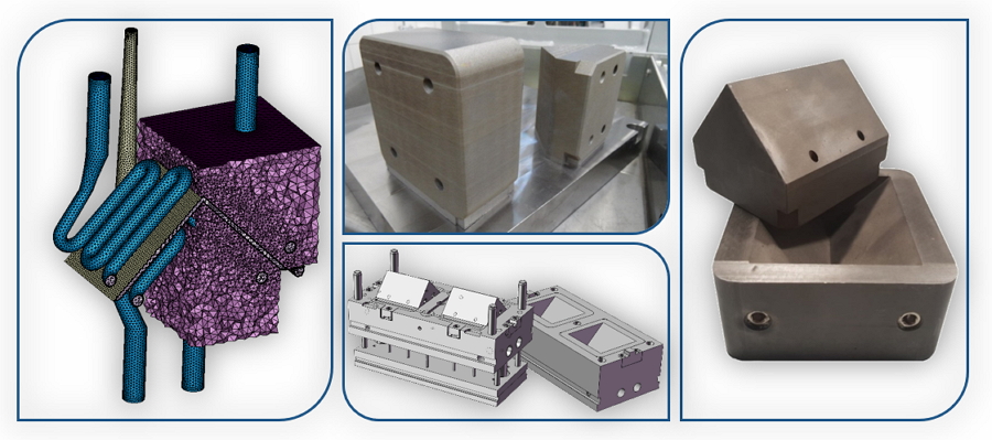
Fig 1. Different types of mold inserts.
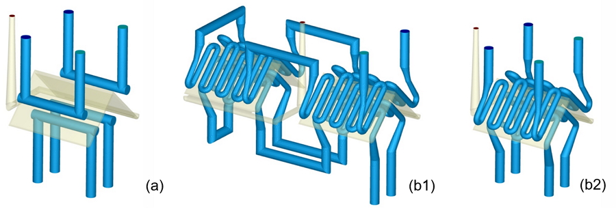
Fig. 2 (a) Conventional and (b) conformal cooling channel: (b1) 2-cavity mold, (b2) only one cavity
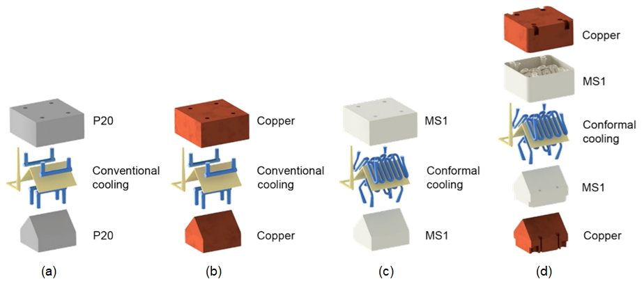
Fig. 3 Different mold inserts used for experiments: (a) P20 steel with conventional cooling, (b) Copper with conventional cooling, (c) MS1 with conformal cooling, and (d) Hybrid of MS1 and cooper with conformal cooling
Challenges
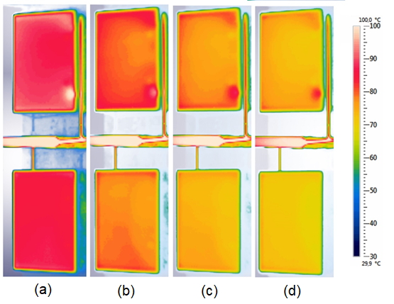
Fig 4. Experiment results: The temperature of the parts at the moment of ejection made with a DMLS (upper) and Hybrid (lower) mold insert after (a) 4 sec (b) 5 sec (c) 5.5 sec and (d) 6 sec cooling time
Solutions
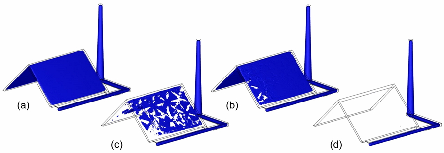
Fig 5. Isosurface of the part at ejection temperature (84°C) in simulations: (a) t = 9.95 s (b) t = 10.95 s (c) t = 11.95 s and (d) t = 12.95 s after the cycle started

Fig. 6 Surface temperature in simulation results after the mold was opened: (a) t = 0 s (b) t = 1.5 s (c) t = 3 s and (d) t = 4.5 s
Benefits
Case Study
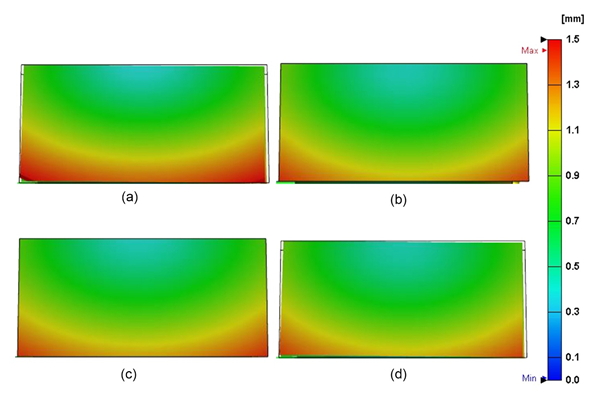
Fig. 7 Simulated warpage of the parts made with the (a) P20 (b) copper (c) DMLS and (d) hybrid mold inserts.
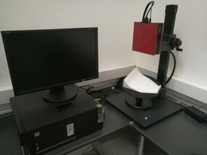
Fig. 8 GOM ATOS
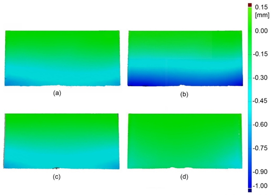
Fig. 9 The measured warpage of the parts made with (a) P20 (b) Copper (c) DMLS (upper) and (d) Hybrid mold inserts
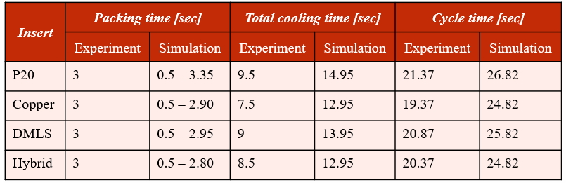
Fig. 10 Experiment vs. Simulation Results
Results